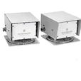
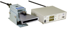
PHV-10

PHV-10 LED type High performance design with using LED
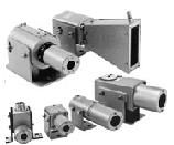
Sensors for Iron and Steel Industry
Optical fiber type CMD

Feature
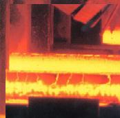
- This is a new optical fiber type CMD using LED as light source. This equipment is composed of transmitter(Sensor head, heat-resistance fiber and amplifier) and receiver and detects steel material which passes through between them.
- This doesn't specify power source. It is capable of being used within the scope of 100 to 240VAC.
- Water-cooling or air-purge isn't required for sensor head because non-air dust purge hood is applied.
- 8-point LED display unable to monitor the margin and emitting state.
- Warning output is provided.
Specifications
|
Model No. |
Amplifier : PHV-10P(Projector), PHV-10A(Receiver) |
|
Detectable objects |
Steel material withφ30mm or more(FHM-201) |
|
Detecting distance |
20m((Detection margin : 80 times or more at 20m*2) |
|
Power source |
100 to 240VAC(+10%, -15%, 50/60Hz) |
|
Power consumption |
Projector : 4VA or less, Receiver : 5.5VA or less |
|
Control output |
1C relay contact(250VAC 3A, 30VDC 5A, COSφ=1), |
|
Warning output |
|
|
Light-emitting amount Lowering output |
|
|
Analog voltage output |
DC voltage output in proportion to light-reception amount(Saturated value 10V or more but do not use it except for adjustment) |
|
Response time |
Contact output : 10msec or less, photo-coupler output : 3msec or less |
|
Operating mode |
Changeover of DARK-ON/LIGHT-ON |
|
Connection |
Connector type(Cable 2m) |
|
Fiber unit characteristics |
Allowable bending radius : 100mm, Max. pressure : 784MPa, Tension strength : 490N |
|
Ambient illuminance |
Incandescent lamp : 10,000lx |
|
Ambient temperature |
Amplifier:-10 degrees C to +55 degrees C, |
|
Ambient humidity |
45 to 85%RH(Not icing) |
|
Insulation resistance |
20MΩ or more(Between power/output contact and case by 1,000V megger) |
|
Withstand voltage |
1,500VAC/min. (Between power/output contact and case) |
|
Vibration resistance |
10 to 55Hz Double amplitude 1.5mm Each 2 hour in X, Y and Z directions |
|
Impact resistance |
490m/s2, Each 3 time in X, Y and Z directions |
|
Protective structure |
Amplifier : IP64(IEC standard) |
|
Case |
Amplifier : Aluminum die-casting, Sensor head : Aluminum |
|
Weight |
Amplifier : Approx. 950g |
*1 3m, 15m and 20m type are also available.
*2 In case of using FHV-321 and FHM-211
*PhotoMOS relay type is also available.
Characteristic data(Typical example)
Steel temperature characteristics

External dimension


Connection
Projector


Light-projecting amount lowering output
|
Operating mode |
NOMAL |
ABNOMAL |
|||||
|
Pin No. of connector |
5-6 |
9-10 |
10-11 |
5-6 |
9-10 |
10-11 |
|
|
Power-OFF state |
OFF |
OPEN |
CLOSE |
OFF |
OPEN |
CLOSE |
|
|
Power-ON state |
When normal |
ON |
CLOSE |
OPEN |
OFF |
OPEN |
CLOSE |
|
When troubled |
OFF |
OPEN |
CLOSE |
ON |
CLOSE |
OPEN |
|
Receiver


Control output(Changeover by inner switch)
|
Operating mode |
Light-ON |
Dark-ON |
|||||
|
Pin No. of connector |
5-6 |
9-10 |
10-11 |
5-6 |
9-10 |
10-11 |
|
|
Power-OFF state |
OFF |
OPEN |
CLOSE |
OFF |
OPEN |
CLOSE |
|
|
Power-ON state |
When light-entering |
ON |
CLOSE |
OPEN |
OFF |
OPEN |
CLOSE |
|
When light-interrupting |
OFF |
OPEN |
CLOSE |
ON |
CLOSE |
OPEN |
|
Warning output
|
Pin No. of connector |
7-8 |
12-13 |
13-14 |
|
|
Power-OFF state |
OFF |
OPEN |
CLOSE |
|
|
Power-ON state |
When normal |
ON |
CLOSE |
OPEN |
|
When troubled |
OFF |
OPEN |
CLOSE |
|
HOKUYO MARKASINA A?T ?R?N GRUPLARI